Hello and welcome to whatishifi blog which I hope you explore and find it interesting.
Reason for this post is somehow obvious, me and Panos bought a Sansui Z-9000 receiver just for the fun of it. We hadn't noticed this model before, but we were impressed by it's retrosexual looks and the size it has when we saw it for sale, so we just bought it to play with it.
 |
| The mighty Sansui. |
Sansui Z-9000 comes after an era that a wattage war was happening among the manufactures, so it is rather strong as an amp, 2x120Watt RMS at 8Ω and capable to also drive 4Ω speakers, something that back then (1983) was not found at every piece of gear. Digital tuner was also new, to be honest this is for me the first vintage digital receiver I see. It is loaded with a lot of features; 3 speaker outputs, built in equalizer with by-pass, reverb function with display, radio station memories, clock and timer, MM MC phono input, pre out / main in, 2 tape loops. The built quality is very impressive both inside and outside, with Nichicon capacitors (including bipolar ones) and OMRON relays. The fact that you can remove the bottom plate and that the boards are connected with connectors really helps at repairs. So far, bravo Sansui! However, circuit implementation is unnecessarily complicated and service manual not very accurate.
The unit we bought was at an impressively good looking condition, however we knew form the beginning that we had to deal with these problems:
- Some indication lamps where burned.
- The FM digital tuner was moving in steps of 0.2 MHz, that is, the tuning would jump from 92.0 to 92.2 when it should move with 0.05 steps in Greece.
- After unplugging the unit, time and radio station memory were instantly reset.
- Before purchasing it and during examination, we also discovered that one channel would randomly mute and unmute at will.
- After purchasing it, we discovered that the two main big capacitors have leaked.
But let's take first thing first.
After purchasing it, we opened the wooden top to take an optical inspection; everything was looking normal. We made a fast listening test with a good recording, the sound was much more pleasing than what we expected. With an average recording, the sound was swomehow bad.
We decided to investigate the tuning issue first. A sticker on the top cover as well a text on the owner's manual was saying that the tuning for AM was adjusted accordingly in regards to where this unit would be sold and if we experience any irregular behaviour, we should contact the dealer. The fact that this model is a multi voltage model (you can change the voltage by plugging and unplugging some wires inside the unit) made us almost certain that there should be some kind of an easy adjustment in order to make the FM radio behave normal for our area. We started searching the tuner board where we indeed found a switch; however, nothing seemed to change.
 |
| The mysterious switch on the tuner board. (Update: according to a discussion at f/b, this switch is for "FM deemphasis. 50uSec for Europe, 75uSec for U.S. Plays fine either way, the 50 setting will sound a little brighter". |
We paused the investigation for the tuner and we proceeded by removing the front plate in order to have a look at what kind of lamps we will need. As Panos was looking the schematics, it became apparent that there was another micro-switch at the top of the right front board.
 |
| The microswitch that adjusts the FM tuning steps at the Sansui Z-9000 receiver as seen from the top with the wooden case removed. |
We found it (you only need to take off the top wooden cover in order to access it), but it was saying again that it affects the AM reception; however moving it (please do so with the unit off) the digital display changed from 92.0 to 92.00 and the desired 0.05 step was activated!
 |
| If you take the face out, you will see printed on the board that Sansui insists that this switch affects AM tuning, which is wrong. |
We were happy as little kids. Still, we noticed something else: if you tune at a station that is at 92.00, the display indicates 92.05 as the frequency. Never mind, we choose not to touch anything at the tuner board; we can live with this. (Update: after a visit to a technician, this issue was also fixed but we don't know what he did).
Having the tuning issue solved, we explored more carefully the issue of muting sound at one channel. This phenomenon was present also at headphones out as well as at the pre out RCA, indicating that the power amp is OK and we should focus at the pre amp circuits. After a while, it became clear that this symptom was affected by pressing the TAPE-2 input switch. Soon we heard a relay clicking when this switch was pressed, we followed this sound and we understood that we had to open the bottom cover in order to locate it.
 |
| It is so convenient to be able to remove the bottom plate of a Hi-Fi device. |
Indeed, at the bottom we found 4 relays. You can easily open their cover and so we did. We carefully sprayed contact lubrication spray and we pressed for some times all the buttons needed in order to engage and disengage the relays. After that we sprayed contact cleaner and we sprayed again contact lubrication at the now clean relays; voilà, problem solved - or so we thought back then.
 |
| The input relays of the Sansui Z-9000 can be easily reached and maintained. |
However, as we were happy solving two problems at the very same evening we purchased this retrosexual monster, we noticed something else: a part of a rail at the main board was missing.
 |
| This is not a good sign. |
This was under one of the two big power capacitors which is a rather clear indication of what had happened. Indeed, looking closer we saw that at the main board where these capacitors are placed there are two holes underneath them and these two holes were looking dirty. We also spotted same kind of dirt at the inside of the bottom plate we removed so it was official; these two capacitors were dead and we were lucky that we found out about it before a major damage had occurred.
 |
| Sansui Z-9000 leaking main capacitors |
 |
| Proof of stains. I remember a similar case with an American president. |
So, more fun for us! We spotted another capacitor with a greenish color at his top and the "glue of death" at the bottom.
 |
| You can get rid of this glue with some swabs and alcohol. |
We decided to remove it in order to get rid of the glue (because over time this glue might become conductive and can potentially cause troubles) and measure this capacitor. It was a bit above the 50% of it's capacitance. So, we had to make a decision. After some discussions and thoughts, we decided to:
- Change all capacitors that are the same type with the one we took out, that is with a greenish color on top.
- From the caps left, change all electrolytic capacitors that are involved at any power supply.
- As an attempt for a possible sound improvement, change all electrolytic capacitors that are in the signal path with the best bipolar we could find and fit.
Our first priority was to protect and preserve this Sansui from possible future fatal damages and this will be accomplished by changing all the capacitors that are involved at the power supply at any board. Also, we decided to replace all the capacitors that are in the signal path, in order to help the device perform a bit better. The best thing to do, was to replace every single capacitor at all the boards (which are quite a lot) but we felt that replacing only the ones involved at the power supply and the signal path is the best compromise for us: the receiver will stay healthy and will get a performance boost while the labor involved for this remains feasible. After all, we will be securing the long live of the receiver, you can change whatever other capacitor you fell like it, when you feel like it.
In this process we needed to verify in the schematics which capacitors were involved at the power supply and which in the signal path.
As always, one of us would see the actual capacitor on the board and with the aid of magnifying glasses would read the values (including temperature), put a mark on the top of the cap (so we know with which caps we are "done") and the other would search at the not so clear schematics what is the role of the particular capacitor and order the optimum replacement. Since sometimes the replacement capacitor is not an exact match but a better one, or there are multiple types of caps with same values, you better keep notes of what you actually order and the position you plan installing it; at this project we didn't and it took more time to find out what goes where than actually replacing the cap. If you order from Mouser, you can include the position of each capacitor in your order and they will come in separate bags with this position printed on the label. Other trusty on line sources for capacitors (except your local store) are TME and Digi-Key.
At this point, let me make some general comments regarding caps. We have found caps at 90's amps to be OK (Luxman M-03). We have found that the Nichicon power capacitors at this 1983 Sansui Z-9000 receiver were totally out of specs, while Nichicon signal capacitors at the same receiver were pretty much OK, defying aging. Eventually, an electrolytic capacitor will need replacement but we don't know when or where. Also, we don't know the effect an old capacitor has at the sound. To make a long story short, don't get hysterical regarding capacitors. Just keep in mind that capacitors involved in the power supply need to be healthy, otherwise you might jeopardize your equipment.
Also, changing capacitors will most probably alter the character of the sound of the equipment. I was discussing this with a friend who is at the HiFi and speaker repair business for some decades now (and he is 100% down to earth with HiFi), and he told me that back in the 90's when he had a Pioneer A-07 amp, he got the best super duper Nippon Chemi-Con for audio capacitors he could find and replaced the original 4 big power capacitors that this amp had. After that, the amp was sounding a bit on the bright side. Thinking that this might be just his idea, he installed the original capacitors back; this way he confirmed that at that system he had, the sound was better with the original capacitors, event though they were "inferior". Please mind that I wouldn't expect the sound to change by changing the capacitors at this particular position but it did; so, think what happens when you change caps at the signal path. So, once more, don't get hysterical regarding capacitors. Ideally we would need to try various capacitors at various positions at an amp one by one and see what happens but this is not very practical.
 |
| Αlea jacta est. Every capacitor that you see that is green on top, will be replaced. Every capacitor involved in the power supply at any level, will be replaced. One of us was siting on the laptop looking at the schematics, the other one would physically find the capacitor on the board, read the values and mark it so we can move on to the next one. |
After spotting all the caps that are going for replacement, we choose low ESR for most of them, Nichicon Gold Tune for the two big ones and bipolar for the ones involved in the signal path.
On choosing the capacitors you will use, I suggest you to go for a good brand like Nichicon, Kemet, Rubycon, Elna, Vishay or Nippon Chemi-Con. For the ones used in power supply rails, you need low ESR models. For ones used in power supply rails but directly related with the sound (like the big caps that feed the power amp section), it is logical to go for audio capacitors. For caps in the signal path, you better use bipolar / MUSE electrolytic caps or film / WIMA caps - the film ones have 10% tolerance compared to 20% of electrolytic. If you go for different type / higher voltage / higher temperature capacitors (the benefit of generally installing a higher voltage or a higher temperature capacitor at positions that get heated, is that it will almost certainly live longer), make sure they will physically fit; however, if you are replacing old caps, it is nice to know that new caps are much smaller in size. Same thing is to be considered regarding increasing the capacitance of caps used in the power supply, plus understanding if the bridge rectifier is capable to deal with the increased power demands of initially charging the beefier caps when you turn on your equipment.
 |
| Look how smaller in size capacitors have become; the one on the right has bigger capacitance and still is smaller in size. |
Waiting for the capacitors to be delivered and understanding that the voltage STK is also another component we don't want to jeopardize failing, in order to be on the safe side, we took it apart from it's aluminum cooler and after cleaning it, we replaced the heat paste. Please note that the old paste eventually was not in a critical condition.
 |
| First we gently removed the two screws that hold the STK at it's base. |
 |
| By removing the aluminium cooler from the STK base, you gain access to the screw that holds this base to the main board. |
 |
| With the STK base and cooler fully removed, cleaning the old thermal paste and applying a fresh one on both sides is easy. |
Let's take a more detailed look at everything we have done.
Replacing caps at the 3804 mainboard.
As I said, we decided to change all the electrolytic caps that are involved in power supply and all the electrolytic caps with the greenish top, no matter what their role is.
- C3 & C4, 35V 100μF.
- C7 & C8, these are related with the STK, we used Fine Gold 1000μF 80V. Original were 1000μF 50V.
- C10 & C13, 220μF 35V.
- C15, 330μF 25V.
- C19, 1000μF 35V. Original was 470μF.
- C21 & C22, 100μF 25V.
- C27, 47μF 50V.
- MC8, 2200μF 35V
- MC9, 1000μF 35V.
- MC16, C12, C14, C23 & C24 10μF 50V.
As I mentioned earlier, we decided to go for Nichicon Gold Tune for the two main power capacitors, same value like the originals (10000μF 80V). Not that there were many alternatives, this capacitor replacement is not so straight forward. You see, the original Nichicon capacitors this unit had, were a 5 leg type, an obsolete design. As if this was not enough, the first couple of Nichicon Gold Tune caps that arrived were rattling; if you was holding the cap in your hand and shake it a bit, you could feel something moving inside. We said that to Mouser; they have excellent customer care and they send another couple free of charge. But again, one of the two units had the same behavior. We said that to Mouser and to their credit they credited the one unit that was rattling. We also contacted Nichicon, we were told that caps do not look suspicious or counterfeit and this probably has been caused due to bad transportation. For sure, we can't blame Mouser for bad transportation since the caps were packaged 100% properly and at a way they could stand severe shocks. Anyway, since we had some spare units we decided to open one:


Seems like the glue failed to keep in contact with the aluminum housing. However, the capacitors were measuring and behaving absolutely normally, so we decided to go ahead and use them.
Have a look at the photos below and you will understand what we did in order to fit the new capacitors in position; please note that we took all the necessary precautions regarding handling and displacing capacitor chemicals.
 |
| This is the Sansui Z-9000 original main capacitor. It has 5 pins, with the 3 of them used solely for the physical support. |


 |
| With the appropriate drill, take out the two pins used for the electrical connection and leave the three ones that are used for the physical support. |
 |
| This is our new capacitor. |
 |
| Now it is the time to mark + & - ! |

 |
| Frankenstein capacitor, but it works. |
As always and in order to avoid any dramas, take care for correct polarity connection.
Last but not least, we repaired / reinforced the damaged rails.

Changing the illumination and indicator lamps and cleaning the display at a Sansui Z-9000:
In order to change the illumination lamps that are used to illuminate the indications at the central display window or the reverb display, you only need to remove the wooden top cover. These lamps can be pulled out and be replaced without any other fuss; the type is 8V 0.1A 4x10mm.
In order to clean the display or change any other lamps, you obviously need to also remove the face plate and the display window. This is an easy process, with the top wooden case off unscrew the 3 screws on top and the 3 screws on the bottom that hold the aluminum face plate. Pull out the Mic Mixing, Balance & Reverb cylindrical knobs and then pull the face out. Note: officially you also need to pull out the black clock knob but at our unit is was stuck and the base that is holing it at the face plate had come off, so we left it this way, meaning it was left in position.
Now in order to pull out the central display window, you will also have to take out the big bottom cover plate (the one with the 12 screws) in order to have access to 2 clips that hold the display. Remember to pull out the two illuminating lamps from the top, unscrew the 2 screws at the top that hold the display face and push gently the two clips at the bottom. Now you can also clean the display.
 |
| The two holders of the display as they are seen after removing the bottom plate. |
 |
| Be carful not to brake these holding teeth. |
In order to also change any lamps, you will need some patience. If the lamps need replacing are located at the right front board, things are easier. If the lamps are located at the left front board, you will also need to loosen the right board in order to release a cable.
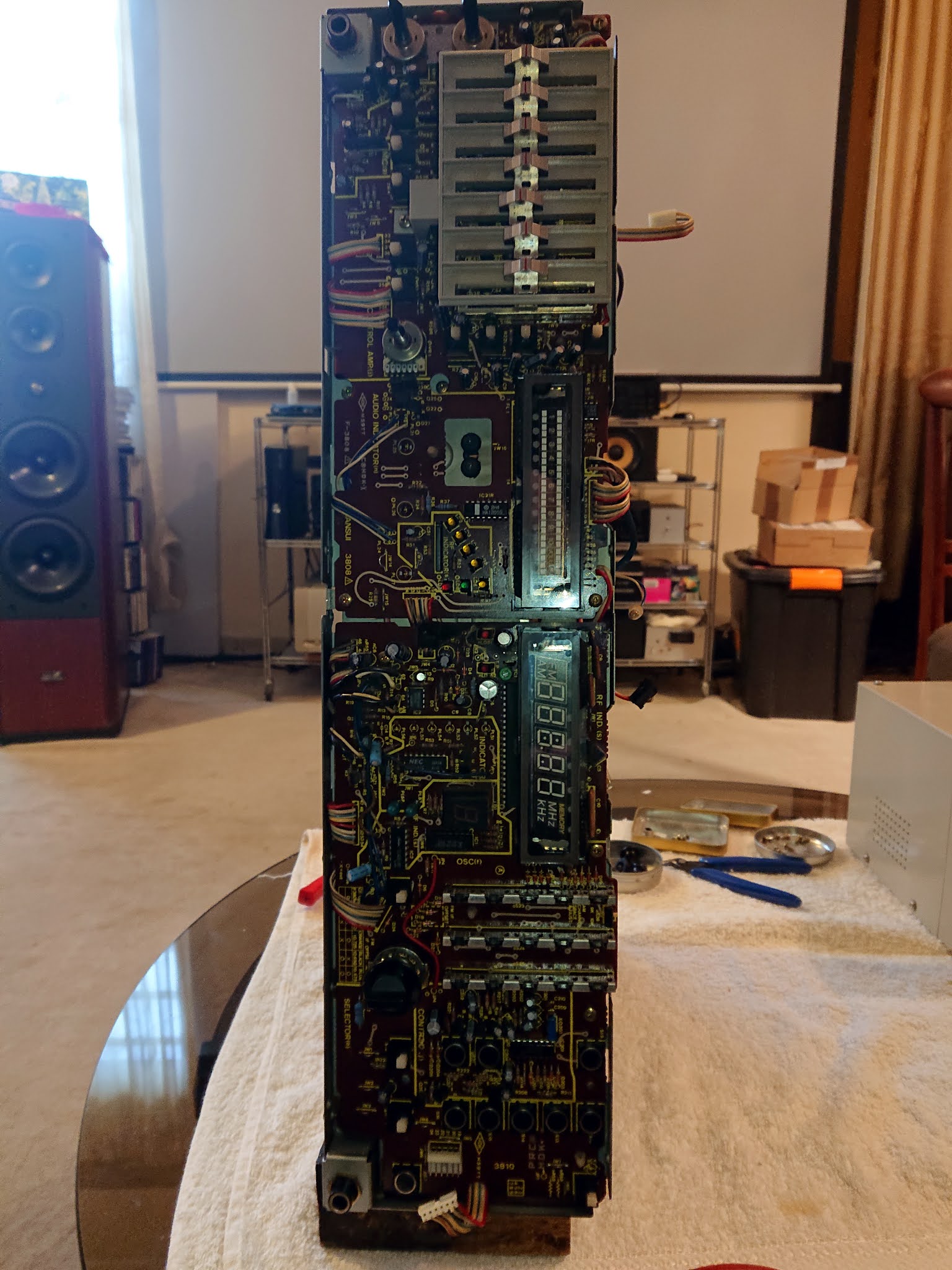 |
| This is what you see after removing the face of a Sansui Z-9000 receiver. |
In order to release the front right board 3810, pull out the connector located at the right. Then unscrew the 4 screws that hold this board - take a mental note where these screws are located, because there are more than 4 holes and you need to put back the screws at the right holes. Next step is to release the board from two plastic base clip holders by pressing with an appropriate tool the plastic clip top of these bases that protrude from the board. After the board is free, you have to gently pull it towards the front and slide it a bit towards the right side of the receiver so it will also be released from the metallic tooth at the top middle that holds it; now you can have access to the back of the board in order to unsolder and solder the lamps. By the way, these lamps are 8V 0.1A 4x10mm that can be easily found - you can re-use the same black bases that the original lamps are installed, so no worries about the base.
 |
| After the board is free from everything else holding it, you have to slide it in order to get out of this metallic holder. |
 |
| No tight cables for this board, you can easily have access and repair what you need to repair. |
Since we already had access at this board, we decided to replace every cap that is involved at the power supply section. Please note that at this board there is the PLL synthesizer & control chip iC1 PD1704C-011 which if malfunctions, nothing will work. We chosen 105°C capacitors, since we noticed some heat black smoky marks on this board, coming from the lamps and a voltage regulator this board has.
- fC1, 10μF, 16V
- fC2, 47μF, 16V
- fC6, 470μF, 6.3V no super cap here!!!! But now the unit holds station memory / time for a while when unplugged.
- fC8, 4.7μF, 50V
- fC13, 22μF, 16V
We noticed that the nC6 (47μF, 16V) had become smoky black from the nearby nR55 resistor, so we decided to also replace it. However, this proved unnecessary; both the cap and the resistor was measuring spot on.
Also, since we saw some black smoky heat marks coming from the fIC3 6V voltage regulator, we decided to replace it with a bigger one in order to keep things cooler; we used an BA17806T.
If you also need to make repairs to the left 3808 front board, it is a bit more complicated to take it out. Again, you will have to unscrew the 4 screws that hold it, please mind the top left one is the only one with a washer. Again, you have to release it also from two plastic base clips. Then you have to release the two plastic teeth that hold the plastic cover of the equalizer sliders.
 |
| The two plastic teeth holding the equalizer face plate. |
Now you have to unplug two cable connectors from the main board side that connect this front board to the main board and cut loose all the other cables from the tire ups that hold them, in order to gain some freedom of move. There is also another cable connector with black plug that goes to the tuner board, but the cable is rather long. Also, free the cable that connects it with the right board from the metallic cable holders. Now you have to gently slide the board towards the right side of the receiver, so it can be released from the last two things that hold it and are shown in the two pictures below:
 |
| This is located on the left side down... |
 |
| and this metallic tooth is located at the bottom left. |
After that, you have access to change the lamps of the Sansui Z-9000 at both boards. Also, you can spray some spray at the knobs and at the equalizer sliders.
 |
| Our unit ready to be repaired. |
In order to put everything back together, just make the exact opposite movements with the exact opposite order.
Please note hat we couldn't find any power supply related capacitors on this board.
 |
| Nice and clean display. |
Replacing caps at the 3962 pre amp out / power amp in board.
This board can be easily released by only one screw that you will find between the RCA connectors. Here all caps are involved in the signal path, so we went for bipolar.
 |
| This input board was missing from the schematics. |
- C303 & C304, 1μF 50V B.P.
- C305 & C306, 10μF 25V B.P. MUSE.
- C307 & C308, 2.2μF 35V B.P.
At the part list, there were also other capacitors, but in the actual board our unit has, there were not such capacitor positions. Please note that this board appears at the service manual, but not at the schematics.
Replacing caps at the 3807 input / phono board (the one with the input relays).
In order to release board 3807, unscrew the 4 screws that hold the board plus 3 more black screws at the back in the RCA connectors. Removing this board provides access to the tuner 3806 board.

- 2x C2, bipolar 4.7μF 50V.
- 2x C4, 1000μF 6.3V; these were "greenish" type.
- C9 & C10, 47μF 16V.
Replacing caps at the 3806 tuner board.

In order to have access at the bottom of this board, you have to release 3807 input / phono board first.
- C43, 220μF 15V, not involved in the PS section, but was of the "greenish" type.
- C51, 100μF 16V.
- C52, 220μF 25V. This is near the heat sink, it is a good idea to use 105C.
Please not that C54, even though physically placed at the power supply section of the 3806 tuner board, is not related with a power rail.
 |
| At last, recapped! |
Replacing all these capacitors took a while and stupidly in the meanwhile we didn't test our unit. When we plugged it in, a big disappointment was waiting for us. Our unit proved to be a bit bitchy and again had various issues, the most severe one was that it stayed at protection mode.
At the beginning we were confused because we couldn't get sound from anywhere; headphones, rec out or pre out. We mistakably assumed that we were dealing with one problem, but after a lot of checking, we also found out that the input relays were stuck again; we could see some green oxidation inside them. We opened them to do another cleaning, now by also using a piece of paper for a soft rubbing of these delicate relay contacts, finishing with some lubricating contact spray. At one relay (Tape 2) we also pressed gently and bended just a bit the stable side of the contact, which seemed to correct the problem of no sound at one channel when the Tape 2 input was selected.
 |
| Cleaning with some paper and contact cleaner. Also, gently bending just a bit the edge of the contact that you see above the paper solved the problem for good. |
Now we got sound from all the pre outs and also after the transistors and before the non engaging speaker relays, but the insisting protection mode drove us nuts. We stubbornly kept assuming that we did something wrong with the capacitor exchange that was triggering the protection. After a lot of testing and checking, we gave the unit to our guru technician; eventually the fault was irrelevant with our restoration. During the restoration period, a resistance and /or a capacitor at the protection circuit decided to fail, so the protection mode was stuck. Unfortunately we do not know which exact parts he changed, neither if they where at the mainboard's protection section or at the input board protection section.
Anyway, problems solved so we followed the procedures described at the service manual regarding adjusting DC offset and bias. A helpful hint regarding DC offset adjustment that is not mentioned at the manual is that the TP1 is connected with the leg No. 10 of the STK and the TP2 is connected with the No. 9 leg, so you can take measurements from these test points instead of the base of the STK. The DC adjustment is easy and pretty straight forward, the bias needs just a little patience.
Amp gives a prefect square wave and a perfect sinewave, but the sinewave was towards the positive side.
 |
| At last, our unit shines! |
After some stress tests and playback time with small expendable speaker, we were sure that we can trust the receiver so we connected it to our main speakers for sound evaluation.
First impression was that sound is pleasing, not harsh, nothing sounding bothering or disturbing. We were happy to listen to the sound it produces. But after some more critical listening with a Sony CDP-XA50ES tweaked CD player and some reference albums - like Madeleine Peyroux / Bare Bones, Dianna Krall / From This Moment On, Clifford Jordan Quartet – Live at Ethell’s, Massive Attack – Heligoland, Dire Straits / Money for nothing - we understood that we were missing things compared to the sound of our regular system. Low end, although fenomenally deep enough, was lacking authority and in some cases was sounding hollow. Focus was good, soundstage seemed broad enough but still, there were things left to be desired from these albums that we know by heart how they sound and how listening to them at a good system makes you feel. Another awkward thing was that the door bell at track Instead / Madeleine Peyroux sounded almost in the middle instead of far left. We thought that this is the sound of the 80's, technology back then was not mature enough and the usual blah blah blah, so we concluded that this receiver is prefect for casual listening and we called it a day.
However, soon curiosity knocked on our door and we thought to give it a try by taking advantage of Sansui's pre out / power in and using another pre amp. This way we would understand if the limiting factor was the pre amp section and what the power amp section is worth. So, we connected our tweaked Rotel RC-970BX pre amp and we used the same albums that we listened to the previous day.
 |
| Sansui Ζ-9000 testing as a power amp. |
We where wondering if we would be able to spot any differences in sound, but after hitting the play button on the Sony, it was immediately absolutely clear that this combo is totally capable for critical listening. I mean, you can use it as a reference system, it is not that it just sounds better than before or better than what you would expect / think of. The sound was outstanding. The soundstage was enormous, holographic, deep and 3D with distinctive layering. The door bell in Madeleine Peyroux sounded as it should, at the far left. The hollow base was gone. All the little details that you know are there, where there, in a beautiful way. It was one of these cases that we were supposed to listen to one song from each album just to evaluate, but the experience was so pleasant that we left the whole album play and rediscover it. We were so much surprised, that we connected back our reference custom made tube pre amp and the Parasound A-21 power amp, just to make sure we were not exaggerating. We were not; each system was more of a "different" than "better", both of them totally capable for critical listening, both of them making you happy listening to the music, passing the emotions of music to you. Panos appreciated the focus of the reference system, I appreciated the divine placement of Dianna's Krall voice in our listening room of the Sansui / Rotel combo. If we need to find something negative, we can say that Sansui has a sound just a bit on the bright side; still, this is marginal and depends on what you are listening to and of course, your speakers.
So it became obvious that the power section of this amp is pretty outstanding (even though it includes a STK, up to that moment we had no appreciation for them), but the pre section is totally average. Hmm, they knew a lot about sound back in the 80's after all, and this is not the first time we come to this conclusion, in contrary of the common belief that sound has evolved each and every year for all kind of equipment. Of course we have also to admit that it is such a pity that the pre amp section of this unit limits performance so much. We assumed this probably happens due to the op amps the pre amp has, but replacing them is not very easy. You see, they are stupidly placed behind the top right fluorescent display and it needs some courage to take it off and things might go ugly, if an old board trace decides to be adventurous.
So, that's all folks, happy listening as always!
Christos

No comments:
Post a Comment